PAGE

Sabado, Agosto 9, 2014

BLOG 7 - ELECTRICAL CIRCUIT 1

This blog contain about the Mesh analysis and Mesh current analysis.

Mesh analysis


Figure 1: Essential meshes of the planar circuit labeled 1, 2, and 3. R1, R2, R3, 1/sc, and Ls represent the impedance of the resistors, capacitor, and inductor values in the s-domain. Vs and is are the values of the voltage source and current source, respectively.
Mesh analysis (or the mesh current method) is a method that is used to solve planar circuits for the currents (and indirectly the voltages) at any place in the circuit. Planar circuits are circuits that can be drawn on a plane surface with no wires crossing each other. A more general technique, called loop analysis (with the corresponding network variables calledloop currents) can be applied to any circuit, planar or not. Mesh analysis and loop analysis both make use of Kirchhoff’s voltage law to arrive at a set of equations guaranteed to be solvable if the circuit has a solution. Mesh analysis is usually easier to use when the circuit is planar, compared to loop analysis.


Mesh Current Analysis Circuit

mesh current analysis circuit
One simple method of reducing the amount of math’s involved is to analyse the circuit using Kirchoff’s Current Law equations to determine the currents, I1 and I2 flowing in the two resistors. Then there is no need to calculate the current I3 as its just the sum of I1 and I2. So Kirchoff’s second voltage law simply becomes:
  • Equation No 1 :    10 =  50I1 + 40I2
  • Equation No 2 :    20 =  40I1 + 60I2
therefore, one line of math’s calculation have been saved.

Mesh Current Analysis

A more easier method of solving the above circuit is by using Mesh Current Analysis or Loop Analysis which is also sometimes called Maxwell´s Circulating Currents method. Instead of labelling the branch currents we need to label each “closed loop” with a circulating current.
As a general rule of thumb, only label inside loops in a clockwise direction with circulating currents as the aim is to cover all the elements of the circuit at least once. Any required branch current may be found from the appropriate loop or mesh currents as before using Kirchoff´s method.
Another way of simplifying the complete set of Kirchhoff’s equations is the mesh or loop current method. Using this method, Kirchhoff’s current law is satisfied automatically, and the loop equations that we write also satisfy Kirchhoff’s voltage law. Satisfying Kirchhoff’s current law is achieved by assigning closed current loops called mesh or loop currents to each independent loop of the circuit and using these currents to express all the other quantities of the circuit. Since the loop currents are closed, the current that flows into a node must also flow out of the node; so writing node equations with these currents leads to identity.
Let us first consider the method of mesh currents.
We first note that the mesh current method is only applicable for “planar” circuits. Planar circuits have no crossing wires when drawn on a plane. Often, by redrawing a circuit which appears to be non-planar, you can determine that it is, in fact, planar. For non-planar circuits, use the loop current method described later in this chapter.
To explain the idea of mesh currents, imagine the branches of the circuit as “fishing net” and assign a mesh current to each mesh of the net. (Sometimes it is also said that a closed current loop is assigned in each “window” of the circuit.)
The schematic diagram
The “fishing net” or the graph of the circuit
The technique of representing the circuit by a simple drawing, called a graph, is quite powerful. Since Kirchhoff’s laws do not depend on the nature of the components, you can disregard the concrete components and substitute for them simple line segments, called the branches of the graph. Representing circuits by graphs allows us to use the techniques of mathematical graph theory. This helps us explore the topological nature of a circuit and determine the independent loops. Come back later to this site to read more about this topic.

The steps of mesh current analysis:
  1.  Assign a mesh current to each mesh. Although the direction is arbitrary, it is customary to use the clockwise direction.
  2. Apply Kirchhoff’s voltage law (KVL) around each mesh, in the same direction as the mesh currents. If a resistor has two or more mesh currents through it, the total current through the resistor is calculated as the algebraic sum of the mesh currents. In other words, if a current flowing through the resistor has the same direction as the mesh current of the loop, it has a positive sign, otherwise a negative sign in the sum. Voltage sources are taken into account as usual, If their direction is the same as the mesh current, their voltage is taken to be positive, otherwise negative, in the KVL equations. Usually, for current sources, only one mesh current flows through the source, and that current has the same direction as the current of the source. If this is not the case, use the more general loop current method, described later in this paragraph. There is no need to write KVL equations for loops containing mesh currents assigned to current sources.
  3. Solve the resulting loop equations for the mesh currents.
  4. Determine any requested current or voltage in the circuit using the mesh currents.
For example: :    i1 = I1 , i2 = -I2  and  I3 = I1 – I2
We now write Kirchoff’s voltage law equation in the same way as before to solve them but the advantage of this method is that it ensures that the information obtained from the circuit equations is the minimum required to solve the circuit as the information is more general and can easily be put into a matrix form.
For example, consider the circuit from the previous section.
mesh current analysis
These equations can be solved quite quickly by using a single mesh impedance matrix Z. Each element ON the principal diagonal will be “positive” and is the total impedance of each mesh. Where as, each element OFF the principal diagonal will either be “zero” or “negative” and represents the circuit element connecting all the appropriate meshes. This then gives us a matrix of:
mesh current matrix
Where:
  • [ V ]   gives the total battery voltage for loop 1 and then loop 2.
  • [ I ]     states the names of the loop currents which we are trying to find.
  • [ R ]   is called the resistance matrix.
and this gives I1 as -0.143 Amps and I2 as -0.429 Amps
As :    I3 = I1 – I2
The combined current of I3 is therefore given as :   -0.143 – (-0.429) = 0.286 Amps.


LEARNING
 Our topic was all about mesh analysis. I learned was that you need to follow the three steps to determine the mesh analysis such as  Assign a mesh current to each mesh. Although the direction is arbitrary, it is customary to use the clockwise direction. Apply Kirchhoff’s voltage law (KVL) around each mesh, in the same direction as the mesh currents. If a resistor has two or more mesh currents through it, the total current through the resistor is calculated as the algebraic sum of the mesh currents. In other words, if a current flowing through the resistor has the same direction as the mesh current of the loop, it has a positive sign, otherwise a negative sign in the sum. Voltage sources are taken into account as usual, If their direction is the same as the mesh current, their voltage is taken to be positive, otherwise negative, in the KVL equations. Usually, for current sources, only one mesh current flows through the source, and that current has the same direction as the current of the source. If this is not the case, use the more general loop current method, described later in this paragraph. There is no need to write KVL equations for loops containing mesh currents assigned to current sources. Solve the resulting loop equations for the mesh currents. Determine any requested current or voltage in the circuit using the mesh currents. in order to easy for you to answer the problem.

Sabado, Agosto 2, 2014

BLOG 6 - ELECTRICAL CIRCUIT 1

This blog contain about the WYE - DELTA TRANSFORMATION 

WYE - DELTA TRANSFORMATION
A delta-wye transformer is a type of three-phase electric power transformer design that employs delta-connected windings on its primary and wye/star connected windings on its secondary. A neutral wire can be provided on wye output side. It can be a single three-phase transformer, or built from three independent single-phase units. An equivalent term is delta-star transformer. Delta-wye transformers are common in commercial, industrial, and high-density residential locations, to supply three-phase distribution systems.

.


WYE to DELTA and DELTA to WYE CONVERSION

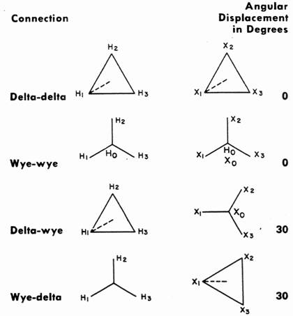
In many circuits, resistors are neither in series nor in parallel, so the rules for series or parallel circuits described in previous chapters cannot be applied. For these circuits, it may be necessary to convert from one circuit form to another to simplify the solution. Two typical circuit configurations that often have these difficulties are the wye (Y) and delta ( D ) circuits. They are also referred to as tee (T) and pi ( P ) circuits, respectively.

Delta and wye circuits:


And the equations for converting from delta to wye:


The equations can be presented in an alternate form based on the total resistance (Rd) of R1, R2, and R3 (as though they were placed in series):

Rd = R1+R2+R3

and:

RA = (R1*R3) / Rd

RB = (R2*R3) / Rd

RC = (R1*R2) / Rd

Wye and delta circuits:


And the equations for converting from wye to delta:


An alternate set of equations can be derived based on the total conductance (Gy) of RA, RB, and RC (as though they were placed in parallel):

Gy = 1/RA+1/RB+1/RC

and:

R1 = RB*RC*Gy

R2 = RA*RC*Gy

R3 = RA*RB*Gy

LEARNING 

This week we tackled about the wye - delta transformation. I learned that the Wye networks are some times called T networks and Delta networks are occasionally called P networks. Wye and Delta Networks have 3 terminal arrangements  commonly used in power systems. T and P 2 of the terminals are connects at one node. The node is a distributed node in the case of the P network.


Linggo, Hulyo 27, 2014

BLOG 5 - ELECTRICAL CIRCUIT 1


Nodal analysis

Kirchhoff's current law is the basis of nodal analysis.

In electric circuits analysis, nodal analysisnode-voltage analysis, or the branch current method is a method of determining the voltage (potential difference) between "nodes" (points where elements or branches connect) in an electrical circuit in terms of the branch currents.
In analyzing a circuit using Kirchhoff's circuit laws, one can either do nodal analysis using Kirchhoff's current law (KCL) or mesh analysis using Kirchhoff's voltage law (KVL). Nodal analysis writes an equation at each electrical node, requiring that the branch currents incident at a node must sum to zero. The branch currents are written in terms of the circuit node voltages. As a consequence, each branch constitutive relation must give current as a function of voltage; an admittance representation. For instance, for a resistor, Ibranch = Vbranch * G, where G (=1/R) is the admittance (conductance) of the resistor.
Nodal analysis is possible when all the circuit elements' branch constitutive relations have an admittance representation. Nodal analysis produces a compact set of equations for the network, which can be solved by hand if small, or can be quickly solved using linear algebra by computer. Because of the compact system of equations, many circuit simulation programs (e.g. SPICE) use nodal analysis as a basis. When elements do not have admittance representations, a more general extension of nodal analysis, modified nodal analysis, can be used.
While simple examples of nodal analysis focus on linear elements, more complex nonlinear networks can also be solved with nodal analysis by using Newton's method to turn the nonlinear problem into a sequence of linear problems.

Steps to determine node voltages:

1. Select a node as the reference node. Assign voltage v1, v2,...., vn-1 to remaining n - 1 nodes. The voltages are referenced with respect to the reference node.
2. Apply KCL to each of the n - 1 non reference nodes. Use Ohm's law to express the branch currents in terms of node voltages.
3. Solve the resulting simultaneous equations to obtain the unknown node voltages.   

  • Current flows from a HIGHER POTENTIAL to a LOWER POTENTIAL in a resistor.
i = vhigher - vlower / R


Nodal analysis with voltage sources


Nodal analysis is the method to determine voltage or current using nodes of the circuit. In nodal analysis we choose node voltage instead of element voltages and hence the equations reduces in this process. We have to consider voltage source is not in this circuit. We have to solve a circuit with n nodes without voltage sources. To solve a circuit using nodal analysis method you must have good knowledge about node branch loop in a circuit. If you have no clear idea read the article then come back here. There are three steps to solve a circuit using nodal analysis

  1. Select a node as a reference node. Give names v1, v2,…. vn-1 to remaining n-1 nodes. All the voltages are the referenced voltages respecting to the reference node.
  1. Apply KCL and KVL to each non reference node. To express the branch currents in terms of node voltages us ohm’s law.
  1. Solve the equations to get unknown node voltages.

First step is to select a reference node. It is also called datum node. The reference node commonly called the ground. It has zero potential.
Nodal analysis voltage source
In circuit the reference node is denoted by any of the three symbols in figure 1. Figure 1 (c) is called a chassis ground because it is used in the case chassis act, enclosure as a reference point in the circuit. Figure 1 (a) and (b) are used when the potential of the earth taken as reference. I use symbol (b).
In two cases nodal analysis can be done with voltage sources.
Case 1: If the voltage source (dependent or independent) is connected between two non-reference nodes, the two non-reference nodes form a generalized node or supernode, we apply both KCL and KVL to determine the node voltages.
Case 2: if a voltage source is connected between the reference node and a non-reference node, we simply set the voltage at the non-reference node equal to the voltage of the voltage source in figure 2 for example,
                                   v= 20V

What is supernode?

A supernode is formed by enclosing a (dependent or independent) voltage source connected between two non-reference nodes and any elements connected in parallel with it.
nodal analysis voltage sources
In figure 2 node 2 and node 3 form a supernode. Applying KCL at super node which are node 2 and 3 we get,
                                        i+ i4  = i2 + i3
problems of nodal analyse
To apply KVL redrawing the figure 2 circuit to figure 3 and going around the loop in the clockwise direction gives,
                       – v2 + 10 + v3 = 0
                        Or  v2 – v3 = 10      ————————— (ii)
From equation (i),(ii) we will obtain node voltages using any solution method.
                              

Sabado, Hulyo 12, 2014

BLOG 4 - ELECTRICAL CIRCUIT 1

THIS BLOG CONTAIN ABOUT SERIES AND PARALLEL RESISTOR


Resistors in Series

   Resistors are said to be connected in Series, when they are daisy chained together in a single line. Since all the current flowing through the first resistor has no other way to go it must also pass through the second resistor and the third and so on. Then, resistors in series have a Common Current flowing through them as the current that flows through one resistor must also flow through the others as it can only take one path.
Then the amount of current that flows through a set of resistors in series will be the same at all points in a series resistor network. For example:
series resistor current
 
In the following example the resistors R1R2 and R3 are all connected together in series between points A and B with a common current, I flowing through them.

Series Resistor Circuit

resistors in series
 
As the resistors are connected together in series the same current passes through each resistor in the chain and the total resistance, RT of the circuit must be equal to the sum of all the individual resistors added together. That is
series resistance equation
and by taking the individual values of the resistors in our simple example above, the total equivalent resistance, REQ is therefore given as:

 REQ = R1 + R2 + R3 = 1kΩ + 2kΩ + 6kΩ = 9kΩ


Equivalent resistance  

Equivalent resistance of any number of resistors connected in series is the sum of the individual resistance.


Resistors in Parallel

Resistors are said to be connected together in “Parallel” when both of their terminals are respectively connected to each terminal of the other resistor or resistors. Unlike the previous series resistor circuit, in a parallel resistor network the circuit current can take more than one path as their are multiple nodes. Then parallel circuits are current dividers.
Since there are multiple paths for the supply current to flow through, the current is not the same at all points in a parallel circuit. However, the voltage drop across all of the resistors in a parallel resistive network is the same. Then, Resistors in Parallel have a Common Voltage across them and this is true for all parallel connected elements.
So we can define a parallel resistive circuit as one where the Resistors are connected to the same two points (or nodes) and is identified by the fact that it has more than one current path connected to a common voltage source. Then in our parallel resistor example below the voltage across resistor R1equals the voltage across resistor R2 which equals the voltage across R3 and which equals the supply voltage. Therefore, for a parallel resistor network this is given as:
parallel resistor voltage
 
In the following resistors in parallel circuit the resistors R1R2 and R3 are all connected together in parallel between the two points A and B as shown.

Parallel Resistor Circuit

resistors in parallel
 
In the previous series resistor network we saw that the total resistance, RT of the circuit was equal to the sum of all the individual resistors added together. For resistors in parallel the equivalent circuit resistance RT is calculated differently.
Here, the reciprocal ( 1/R ) value of the individual resistances are all added together instead of the resistances themselves with the inverse of the algebraic sum giving the equivalent resistance as shown.

Parallel Resistor Equation

parallel resistance
 
Then the inverse of the equivalent resistance of two or more resistors connected in parallel is the algebraic sum of the inverses of the individual resistances. The equivalent resistance is always less than the smallest resistor in the parallel network so the total resistance, RT will always decrease as additional parallel resistors are added.
Parallel resistance gives us a value known as Conductance, symbol G with the units of conductance being the Siemens, symbol S. Conductance is the reciprocal or the inverse of resistance, ( G = 1/R ). To convert conductance back into a resistance value we need to take the reciprocal of the conductance giving us then the total resistance, RT of the resistors in parallel.
We now know that resistors that are connected between the same two points are said to be in parallel. But a parallel resistive circuit can take many forms other than the obvious one given above and here are a few examples of how resistors can be connected together in parallel.

Equivalent Conductance

Equivalent conductance of resistors connected in parallel is the sum of their individual conductance.

Equivalent Resistance

Equivalent resistance of two resistor is equal to the product of their resistance divided by their sum.


LABORATORY

Objective:
  • To measure the voltage and current in a resistor.

Materials:
  • DC Power Supply 

  • Digital Multimeter


  • Resistor

  • Breadboard 


Overview and learning 

   Last Monday we had our quiz it was about ohms law, kirchhoff’s current law (KCL) and kirchhoff’s voltage law (KVL). On the next day we had our laboratory experiment and some of our classmates discussed about bread boarding on how to use. My group mates also discussed about we had our experiment and use material such dc power supply, digital multi meter, connection wires, resistor and bread boarding. We measure voltage and current in order to know if it flows to the bread board. I also learned how to put a resistor and connecting wire in the bread board correctly. Last Wednesday our professor discussed about the series and parallel resistor and last Friday we had our seatwork and it was about parallel and series resistor.